
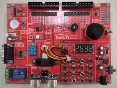
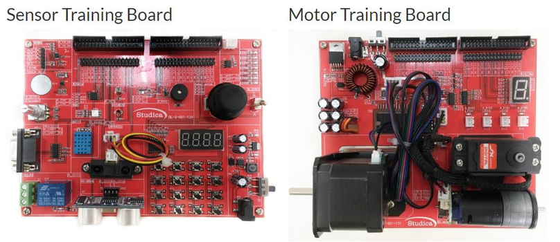
センサートレーニングボード
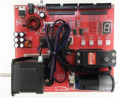
モータートレーニングボード
~NI myRIOやLabVIEWを使った技能五輪&若年者ものづくり競技大会のトレーニングに最適~
センサートレーニングボード
モータートレーニングボード
センサートレーニングボード及びモータートレーニングボードは、NI myRIOとLabVIEWを使ったセンサー及びモーターコントロールの学習に最適です。NI myRIOをコントローラーとして使用し、様々な計測制御に応用することができます。各ボードには、トレーニングに必要なハードウエアが実装されていますので、モーターやセンサーを準備する必要はありません。パワーアダプター、コネクションケーブル等も添付されています。学校教育用にコースウエアも準備しました。
このボードで新たに学んだ学生は、技能五輪移動式ロボット部門(Worldskills)、若年者ものづくり競技大会、WRO(World Robotics Olympiad)等の競技へ挑戦できるだけの技能が充分身に付きます。
| 商品名 |
センサートレーニングボード モータートレーニングボード |
| 価 格 |
各180,000円(税別、送料込) (各198,000円(税込、送料込) ※NI myRIO及びLabVIEWは別売り |
| 納品までの目安 | お問い合わせください。 |
Features,
- 5V five foot small relay;
- SMD LED;
- Touch button based on TTP23;
- Toggle switch;
- Two-way rocker with button function;
- Photoresistor;
- Thermistor;
- Infrared ranging sensor;
- Three-color LED;
- Passive buzzer;
- MAX3232 serial chip;
- MAX3485 serial chip;
- MPU9250 nine-axis chip;
- TSL2561 digital light intensity sensor;
- Based on the TM1637 button and digital tube display;
- DHT11 temperature and humidity sensor;
- HC-SR04 ultrasonic ranging sensor;
- Memory chip W25Q16;
- 19. EC11 rotary switch.
Specifications:
The Sensor Training Board tutorial guide includes the following exercises:
1. Application of common digital I/O port:
a. LED control experiment
b. relay control experiment
c. TTP23 touch switch experiment
d. toggle switch
e. rocker button experiment
2. The application of AD port:
a. photosensitive resistance experiment
b. thermistor experiment
c. 2D rocker experiment
d. infrared distance sensor experiment
3. The use of PWM port:
a. three-color LED experiment
b. passive buzzer experiment
4. The use of serial port:
a. RS232 serial communication experiment
b. RS485 serial communication experiment
5. The use of I2C bus:
a. 9-axis gyroscope using experiments
b. digital light intensity sensor experiments
c. display control button recognition experiment
6. The use of a single bus:
a. DHT11 temperature
b. humidity sensor experiment
7. Clock use:
a. ultrasonic sensor experiment
8. SPI bus use:
a. memory chip W25Q16 experiment
9. Orthogonal coding use:
a. EC11 rotary encoder using experiments
Features,
-
Stepper motor drive circuit;
- 42 stepper motor;
- DC motor drive circuit;
- DC speed reduction motor with orthogonal encoder;
- 180 degree steering gear;
- solenoid valve \ electromagnet drive circuit;
- digital tube;
Specifications:
The Motor Training Board tutorial guide includes the following exercises:
1. Stepper motor motion control:
a. stepping motor forward and reverse experiment
b. stepping motor rotation speed control experiment
c. stepping motor rotation angle control experiment
d. stepping motor acceleration and deceleration control experiment
2. Steering gear motion control:
a. steering gear angle control experiment
3. DC motor motion control:
a. DC motor forward and reverse experiment
b. DC motor speed open loop control experiment
c. DC motor speed detection experiment,
d. DC motor speed closed loop control experiment,
e. DC motor position closed loop control experiment
4. Solenoid valve \ electromagnet control:
a. solenoid valve \ electromagnet on-off control experiment
5. Digital tube display control:
a. digital tube static display experiment